Showing posts with label Transformer. Show all posts

Wednesday, January 2, 2019

January 02, 2019

No Load Transformer And Its Phasor Diagram

Before we start discussing about the no-load condition of a transformer, it is important to first understand that what is meant by no-load.
"A transformer is said to be on no-load when the secondary winding of the transformer is left open-circuited thereby reducing the secondary current to zero".

Transformer At No-Load

During no-load condition, secondary current in the transformer reduces to zero and when an alternating voltage is applied to the primary, a small current I0 flows in the primary winding.
The current I0 is called no-load current of the transformer and it is 3 to 5 percent of the rated primary current.
No-load current is made up of two components Iu and Im.
Iu is called magnetizing component.It magnetizes the core. We can also say that it sets up the flux in the core and therefore Im is in phase with (flux). It is also called reactive or watt less component of no-load current.
The other component Iw supplies the hysteresis and eddy-current losses in the core. It is in the phase with the applied voltage V1. It is also called active or watt full component of no-load current.

Phasor Diagram At No-Load

Phasor diagram for a transformer(real) under no-load condition is shown in the fig. below.

NO-LOAD PHASOR DIAGRAM OF A PRACTICAL TRANSFORMER.

The flux is taken as the reference phasor.  The magnetizing component of the no-load current Im, magnetizes the core i.e, it sets up the flux in the core. Therefore, Im is in phase with the flux.
Iw is in phase with the applied volage, V1.  The phasor sum of Im and Iw is I0. The angle between Iw and I0 is called no-load power factor angle. The power factor on no load is cos(angle).
Iw = I0 . cos(angle)
Im = I0 . cos(angle)
I0 = v{(Iw)+ (Im)}
Since, E1 and E2 are induced by the same flux , therefore E1 and E2 will be in same phase, but E1 and E2 lags behind the flux  by 90 degree. E1 = k. E2 (where k = T1/T2,  T1 & T2 are no. of turns on primary and secondary winding)
E1 and V1 will be opposite to each other due to Lenz Law. If the voltage drop in the primary winding are neglected then V1 will be equal and opposite to the E1.
Power input to the transformer during no-load condition is:
P0 = V1 . I0. cos (angle)

Saturday, December 1, 2018

December 01, 2018

Three Reasons Why Transformer Ratings in KVA.

The transformer is the most important electrical machine which transfers electrical power. If you do not know how a Transformer works then you can read our article Working of a Simple transformer.
Today we are going to know the Three Reasons Why Transformer Ratings in KVA, not KW or KVAR.


Three Reasons Why Transformer Ratings in KVA, Why Transformer Ratings in KVA, not KW.


The three reasons why transformer ratings in KVA given below,


Why Transformer Ratings in KVA.


(1) KVA= KV(killo Volt) * A(ampere)
KW= KV(killo Volt) * A(ampere) * Power factor

We already know that Power factor only depends on the type of Loads like,
  • Inductive Load - Lagging Power factor
  • Capacitive Load - Leading Power Factor
  • Resistive Load - Unity Power Factor
 The Transformer is not a Load, it is a device which can transfer power not consume power. If you think that a Transformer is a Load that's wrong. So as the transformer does not consume power it can only transfer power with increasing and decreasing voltage and current that is why the Transformer ratings in KVA.


(2) When the transformer is designed the manufacturer does not know which type of load will be connected in future. And the power factor depends upon the load. If an Inductive Load is connected then the current will be lag which flows through the secondary winding of the transformer as well as the primary winding of the transformer.


Three Reasons Why Transformer Ratings in KVA, Why Transformer Ratings in KVA, not KW.


We also know that pure inductive and pure capacitive load does not practically exist. Every load has some resistance even it inductive or capacitive. For example, a motor is connected to the transformer which is inductive + resistive. So the motor draws both reactive(KVAR) and active power(KW). So the power supplied by the transformer is the vector sum of reactive(KVAR) power and active power(KW) that is KVA.


(3) The last reason is power loss. Most of the people think that is the main reason "Why Transformer Ratings in KVA" but I will say that is not the main reason. The first and second reason is more important which is described above.
The Copper loss(I2R)  occurs due to the flow of the current in the transformer winding and the Iron or core loss occurs due to the voltage. These losses do not depend on the power factor so that is why the transformer rating in KVA not KW.

This is the Three Reasons Why Transformer Ratings in KVA.


Read Also:


Thank you for visiting the website. keep visiting for more updates.

Sunday, October 14, 2018

October 14, 2018

Transformer can work on DC supply: Right or Wrong

Why Transformer Cannot work on DC Supply?


Transformer can work on DC supply: Right or Wrong, Step down transformer, 12V transformer

If you do not know how a transformer works. For going to the post click on " Working of a simple Transformer"
Now There is a question that is why a Transformer cannot work in DC? Let's know actually what happened when we apply DC supply on the Transformer.


To better understand this topic you should know about Faraday's Law.

      When DC supply is given to the primary winding of the transformer, current flow through the winding and as a result flux is also produced. As in the case of DC, the magnitude, and direction of the current does not change with time it remains constant. So the produced flux which linked both windings also does not change. According to the Faraday's law when the flux linking with the conductor changes the EMF will be induced on that conductor. As in this case, flux does not change so the EMF also is not produced.


     At the time when the switch gets ON the magnitude of the current increases from zero, the flux will be change and EMF will be produced. 
Again at the time when the switch gets OFF the magnitude of the current reduces to zero, the flux will be change and EMF will be produced.
But for both cases, time is very short. It is cleared that a Transformer cannot work on DC supply. 


Now there is a problem that if the DC supply is given to the transformer it's winding will be burn. Because the winding of the transformer has very low resistance. In the case of AC, as there EMF is produced which limits the current flowing through the coil. But in the case of DC, there is no EMF produced so a huge amount of current will be flow through the coil and the coil will be burnout.  
Thank you for visiting the website. keep visiting for more updates.
October 14, 2018

Use Step Down Transformer in different ways.

Use Step Down Transformer in different ways.


In this post, you will learn the Use of Step Down Transformer in different ways.

(1) Have you known, how a Step-down transformer can be used as an Auto Transformer?

Yes, you can use a Step Down Transformer as an Auto Transformer very easily. The circuit diagram is given below. See the circuit diagram carefully and make the circuit properly. The connection of the terminal of the two winding is to be made as the circuit diagram.

As Step Up auto Transformer:


                                   how a Step-down transformer can be used as an Auto Transformer


As Step Down Auto Transformer:


how a Step-down transformer can be used as an Auto Transformer


(2) Let's know how a Step-Down Transformer can be used as Step Up Transformer?

You can use a Step-Down Transformer as a Step Up Transformer very easily using low voltage side as the primary side and high voltage side as the secondary side. But remember that only AC supply is to be given. The voltage can be applied up to the rated voltage.
use a Step Down Transformer as a Step Up Transformer

(3) How a Step Down Transformer can be used as a Current Transformer?

Use the low voltage coil of the Transformer as the primary coil and connect in series with the circuit whose current is to be measured. Connect an ammeter to the high voltage side. By calculating the ratio of the transformer you will measure current.

How a Step Down Transformer can be used as Current Transformer?


Read Also:


Thank you for visiting the website. keep visiting for more updates.
October 14, 2018

Working of a simple transformer.

Working of a simple transformer.


Working of a simple transformer,What is a Transformer, Construction of a Simple Transformer, Working Principle of Transformer, Why Transformer cannot work in DC, Classification of Transformer

What is a Transformer?

A transformer is a stationary electrical device or machine. A transformer can not convert electrical energy into another energy, it only transforms electrical energy from one circuit to another circuit at one voltage level to another voltage level. That's why it's named Transformer. Obviously Transformer work in AC cannot work in DC. The transformer does not change frequency and power. The transformer has no rotating part that's why it is called a stationary device or machine.

Construction of a Simple Transformer:

The transformer has two stationary electric circuits or winding or coils that are coupled magnetically. There is no electrical contact between them. The primary and secondary coil wound on a ferromagnetic material which is called Core. The core transfer the changing magnetic flux from the primary winding or coil to the secondary winding or coil. Each winding or coils of the Transformer has no of turns as per requirement voltage level. 

Working Principle of Transformer:

The transformer works in the principle of mutual induction. The AC supply fed to one of the two coils which are called the primary winding and the other winding which is connected to the load is called secondary winding. So when the alternating current flows in the primary coils, a changing magnetic flux is generated which is linked with both the primary and secondary coil by the core. According to Faraday's laws of electromagnetic induction, an EMF is induced in the secondary winding. This induced EMF drives a current if a load is connected to the secondary winding. The magnitude of the output voltage can be controlled by the ratio of the no. of the primary coil and the secondary coil. Self-Inductance also has seen in the primary winding in a Transformer which limits the flow of current in the primary winding.

Why Transformer cannot work in DC?

If DC supply given to the transformer the produced flux remains constant it not changing so EMF will be not induced. As self-inductance does not appear in the primary winding a huge amount of current will flow through the primary coil(As the coils of the transformer have low resistance), so the winding gets damage. For this reason, the transformer cannot work in DC.

Classification of Transformer:

Based on Construction:

1. Shell Type
2. Core Type
3. Berry Type

Based on Output Voltage:

1. Step-up Transformer
2. Step-down Transformer

Based on Application:

1. Power Transformer
2. Distribution Transformer

Based on the number of Phases:

1. Single Phase Transformer
2. Three Phase Transformer

Read More:


Thank you for visiting the website. keep visiting for more updates.

Thursday, August 16, 2018

August 16, 2018

MCQ ON TRANSFORMER

Hii "Electrical Engineers", lets check that how much you know about the transformers. We are having MCQ which are based on Transformers having one correct option. So let's start.
If you are having any doubt regarding the questions or you are not reaching the answer, then feel free to comment or you can ask me on my facebook page.


Answers to the questions are given at the last.

Q.1  Which of the following losses are not present in the transformer ?
       
      a. Copper loss                                b. Stray loss
      c. Core loss                                    d. None of the above.


Q.2 What is the condition for the maximum efficiency of a transformer for a given power ?

      a. Core loss should be zero.
      
      b. Copper loss should be zero.
  
      c. Total losses of transformer should be zero.

      d. Copper loss of transformer should be equal to the core loss in transformer.

Q.3 Transformer core is laminated in order to reduce ?
     
      a. Eddy current loss                          b. Heat loss

      c. Core loss                                      d. All of the above

Q.4 Transformer has zero voltage regulation at

      a. Unity power factor                         b. Leading power factor

      c. Lagging power factor                      d. Depends upon nature of load

Q.5 The copper loss at half load is 300 W. What will be the copper loss at full load ?

     a. 1200 W       b. 300 W          c. 900 W            d. 600 W

Q.6 The desirable properties of transformer core are

     a. low permeability and low hysteresis loss 

     b. high permeability and high hysteresis loss

     c. high permeability and low hysteresis loss

     d. low permeability and high hysteresis loss

Q.7 Originally the color of silica gel is ______ and after absorbing the moisture it turns _______

     a. Yellow , Blue                                     b. Pink , Blue

     c. Blue , Yellow                                     d. Blue , Pink

Q.8 A transformer has hysteresis of 30 W at 240 V , 60 Hz. Find the hysteresis loss at 200 V -50 Hz ?
      
      a. 20 W             b. 25 W            c. 30 W               d. 35 W

Q.9 The value of Steinmetz constant lies between

     a. 1.5 - 2.5                                            b. 1.0-2.0

     c. 0.5 - 1.5                                            d.  0 - 1.5

Q.10 The saving in conductor material if auto-transformer is used in place of ordinary two winding transformer(where W =weight of copper in ordinary transformer) is

     a. W/K               b. W/(K-1)            c. W/(1-K)           d. K*W

(Take K= Secondary Voltage/Primary Voltage)


------------------------------------ANSWERS-------------------------------------


Q.1 B       Q.2 D      Q.3 A    Q.4 B     Q.5 A     Q.6 C     Q.7 D     Q.8 B

Q.9 A       Q.10 D

Wednesday, August 15, 2018

August 15, 2018

SUMPNER'S TEST

Hii guys in this post we will study about the SUMPNER'S TEST on a transformer. It is also called Regenerative test or Back-to-Back test.

Please read the whole article carefully for understanding it properly

Main objective of the Sumper's test is to check the tranformer efficiency , maximum temperature rise. It is also used to measure the losses in the large transformers.  This method is advantageous for large  transformers because for full load test on large transformers, it would be expensive as a large amount of energy will get wasted during the test. Therefore, large transformers can be tested by SUMPNER'S TEST.


Sumpners test requires requires two identical transformers. Given figure shows the circuit diagram for back-to-back test (Sumpner's test).
Regenerative test of transformer , back to back test of transformer


The primary winding of the  two transformers are connected in parallel and is supplied at rated voltage and frequency. As seen in the figure, a Voltmeter, an ammeter and wattmeter are connected to the input.

The secondary of the transformers are connected in series in phase opposition and voltmeter is connected across them. The range of the voltmeter is twice the voltage of secondary winding. Phase opposition of the winding is checked by this voltmeter. If voltmeter reads 0, it means they are in phase opposition , because both windings have equal voltages but in opposite direction due to which overall voltage in the secondary circuit become 0.
Now if the supply is given to the primary circuit, then the total voltage in secondary circuit will be 0, as discussed above.
There will be no current in the secondary winding and it will behave as secondary is open circuited. Only No-load current will flow in the primary circuit which is measured by the ammeter on the primary side.
Hence , wattmeter on the primary side will read the total Iron losses of the both transformers.


Now, a small voltage is injected in the secondary cicuit with the help of regulating transformer (see the figure). The magnitude of the voltage is adjusted till the ammeter on the secondary side reads the full-load secondary current. This produces the full load copper losses of the both transformers. Thus wattmeter on the secondary side reads the total Full-load copper losses.

Thus with the help of this method we have founded the both losses in the transformer. We have loaded the transformer to the full load but the power taken from the supply is just that it will be only sufficient to supply the losses of both transformers.

Thanks for reading.
Keep sharing and supporting

Tuesday, July 17, 2018

July 17, 2018

PROPERTIES OF IDEAL TRANSFORMER & PHASOR DIAGRAM

Hello friends, in this article we will study about an ideal transformer, its properties and phasor diagram.

PROPERTIES OF AN IDEAL TRANSFORMER.

Ideal transformer is an imaginary transformer which has following properties:

1. Primary and secondary winding of an ideal transformer has negligible resistance.

2. The core of an ideal transformer has infinite permeability so negligible mmf is required to setup the flux in the core.

3. The entire flux produced in the ideal transformer is confined only to the core and links with the two windings only. Hence, its leakage flux and leakage inductance is zero.

4. There are no losses in the transformer due to resistance , hysteresis and eddy current.
    Thus, the efficiency of an ideal transformer is 100%.
Practical transformer does not have such properties.

PHASOR DIAGRAM OF AN IDEAL TRANSFORMER AT NO LOAD.

Given figure shows the phasor diagram of an ideal transformer.
NO-LOAD PHASOR DIAGRAM OF IDEAL TRANSFORMER

Since the transformer is on no load, so the current in the secondary winding is zero i.e. I2 = 0
Here ,V1 = Primary Supply Voltage.
           E1 = Primary Induced Emf.
           I1  = Primary Current.
           �  =  Mutual flux.
          V2 =  Secondary Output Voltage.
          E2 = Secondary Induced Emf.
          

Explanation
 Since the ideal transformer has zero impedance of primary and secondary winding,so voltage induced in the primary winding E1  is equal to the applied voltage V1. But by LENZ'S LAW, E1 is equal and opposite to the V1.

The current I1 drawn from the supply is sufficient to produce an alternating flux � in the core. This current is also called magnetizing current because it magnetizes the core and sets up flux in the core.
So, the current I1 and flux � are in the same phase.

Primary current I1 lags behind the supply voltage V1 by 90 degree.
Since emf induced in primary winding E1 and secondary winding E2  are induced by the same mutual flux, � . So, E1 and E2 are in same direction.

Since the ideal transformer has zero impedance of secondary winding so emf induced in secondary winding E2 and  secondary output voltage V2 will be equal in magnitude and in same direction.

Thanks for reading.
Keep sharing and loving.

Thursday, June 21, 2018

June 21, 2018

TRANSFORMER- Introduction & Basic

Hello friends, welcome to "beingelectricalengineer". In this article, we will study about the basics and introduction to Transformers.

WHAT IS TRANSFORMER ?

A transformer is a static device which consists of two stationary electrical circuits connected to each other by a common magnetic circuit for the purpose of transferring electrical energy between them.
This transfer of electrical energy takes place without the change in frequency.
Transformer works on the principle of Electromagnetic Induction. Electromagnetic Induction is one of the basic law of Electrical Engineering. You can read about Electromagnetic Induction.

Also Read - Electromagnetic Induction

CONSTRUCTION & WORKING PRINCIPLE  OF TRANSFORMER.

A simple transformer consists of two coils wounded on a core as shown in the figure.
BASIC ARRANGEMENT OF SIMPLE TRANSFORMER.

There is no electrical connection between these two coils.

When an alternating voltage source V is applied to the coil 1, an alternating current I1 flows in it. This alternating current produces an alternating magnetic flux in the core. This alternating flux links with the turns  T1 of the coil1 and induces an emf E1 by self-induction.
Thus, all the flux produced by the coil1 also links with the turns T2 of the coil2 and thereby inducing an emf E2 by mutual induction.
If load is connected to the coil2, then an alternating current I2 will flow through it and hence electrical energy will delivered to the load without change in frequency.

Coil1 which receives the electrical energy from the source of a.c supply is called primary winding.

Coil2 which is connected to the load and delivers the energy to the load is called secondary winding.

Note that the transformer can only work with the alternating source. It cannot be used for transferring electrical energy in DC form because transformer works on the principle of Electromagnetic Induction and it requires that current should be alternating in nature. So, transformer cannot work on DC.

EMF EQUATION OF THE TRANSFORMER.

As we have studied that an emf is induced in both the coils or windings. So the magnitude of the emf can be calculated from the emf equation of the transformer which is ;

E = 4.44* � * f * T

Where , E = Magnitude of emf induced.
             � = Maximum flux in webers.
             f  = Frequency in Hertz.
             T = Number of turns in the coil.

With the help of the emf equation, emf induced in the primary as well as secondary winding can be calculated by providing the suitable number of turns.
It shows that winding having higher number number of turns will have higher voltage and hence it is called high voltage  (hv) winding.
Winding having lower number number of turns will also have lower voltage is called low voltage (lv) winding.

TRANSFORMATION RATIO.

The ratio of emf induced in the primary winding to the emf induced in the secondary winding is called transformation ratio. It is denoted by 'k'.

k = E1/E2 = T1/T2;

Transformation ratio can also be defined as the ratio of number of turns of primary winding and number of turns of secondary winding. It is also called turn ratio.


STEP-UP & STEP-DOWN TRANSFORMER.

Transformer in which the secondary voltage is greater than the primary voltage is called step-up transformer.
Step-up transformer has turn ratio smaller than 1.

Transformer in which the secondary voltage is smaller than the primary voltage is called step-down transformer.
Step-down transformer has turn ratio greater than 1.

Transformer having secondary voltage equal to the primary voltage is called isolation transformer or one-to-one transformer.
Such transformer has turn ratio equal to 1.

Thanks for reading.
Keep sharing and loving.


Wednesday, June 6, 2018

June 06, 2018

COOLING OF TRANSFORMER


In this article we will study about the Cooling and Methods of cooling is a transformer.
In rotating machines like motors and generators ,cooling fans are provided . When the machine rotates, the fan causes the circulation of air and hence provides necessary cooling.
But as we know, transformer is a static machine and cooling is difficult. When transformer is working some heat is always produced due to copper losses.

The removal of heat from the winding of transformer is called the Cooling of Transformer.

Cooling is important for every machine whether it is an engine, transformer or computer etc.
Cooling increases the efficiency of the machines.
Same is true for Humans also, suppose you are made to work at temperature above 40 degree celsius, it would a very tough condition for you.
Therefore, some means are taken to avoid the high temperature of the winding . The different methods of cooling of transformer are ;

TYPES OF COOLING OF TRANSFORMER

Cooling of transformer depends upon the type of transformer whether it is an oil immersed transformer or a dry transformer.

For Dry type Transformer
Dry type Transformer are the transformer which does not have any liquid like oil or silicone in it. Such transformers are used upto lower voltage rating and in areas which are having high moisture content.
Such transformers have following methods of cooling.

1. Air Natural Cooling.
2. Air Blast Cooling.

1. Air Natural Cooling-  This cooling is used for small transformer upto voltage rating of 10 to 15 kV. In this method , only natural circulation of air without using any fan, blower etc is used for cooling.
The surface area of the core and  transformer winding is increased to dissipate the heat generated.
Fins are made on the body of transformer similar to that in an engine to increase it's surface exposure area.
Fins are provided on the main tank of
transformer to increase it's surface exposure.


2. Air Blast Cooling- We can say that it is the type of artificial cooling because the forced air is used for cooling purposes.
In this method, transformer is placed over an air chamber and air is maintained at a sufficient pressure with the help of blowers. The air is forced through core and winding of transformer.
Air Blast Cooling with fan provided.

Use of this method of cooling is preferred for the transformer installed in the substation located in thickly populated areas, where oil is considered as fire hazard.

For Oil Immersed Transformer
Oil Immersed Transformer are used for higher voltage ratings. In such transformers, core and winding of transformers are immersed in the "transformer oil", hence it's name.
Cooling methods used in such transformers are:

1.Oil immersed Natural Cooling.
2. Oil immersed water Cooling.
3. Oil immersed air Blast Cooling.
4. Forced Oil Immersed Natural Cooling.

1. Oil Immersed Natural Cooling- In this system, only transformer oil is used for cooling as well as insulation purposes. The oil takes away the heat from core and winding and gives it to the tank surface ,from where the air takes away the heat.
Transformer is filled with oil for cooling.
Oil Immersed Natural Cooling.

To make this system more effective, the surface area of tank is increased . Due to the heat produced by transformer, the oil circulates through pipes, tubes and tanks. The hot oil, being lighter in weight and it goes up and hence natural circulation of oil takes place.

2. Oil Immersed Water Cooling- This is the another method of cooling for the transformer of ratings above 500kVA.
Heat produced in the main tank is taken away by the transformer oil. To dissipate the heat more fastly from the oil to the surrounding , radiator spiral pipes are provided. Water is circulated through these pipes .It absorbs the heat from the oil. Water itself becomes hot and thus reducing  the temperature of the oil, which in turn reduces the transformer's temperature.
Oil Immersed Water Cooling.

But in this method there is always a risk of leakage of water through the pipes. Even a small leakage of water can increase the moisture content of the oil.

3. Oil Immersed Air Blast Cooling- In this method of cooling, the core and winding is immersed in the oil and in addition to this ,air is forced over the surface with the help of fans and blowers.
Broadly speaking, this method is the combination of Oil Immersed Natural Cooling and Air Blast Cooling.

4. Forced Oil Immersed Natural Cooling- In this method of cooling, the core and winding are immersed in the transformer oil as usual. As well as the oil in the main tank is circulated with the help of motor driven pump. This pump forces the oil in the main tank and circulates in it.

So Friends, thanks for reading.
If any doubt or query, please comment.
Keep sharing and supporting.

Monday, May 7, 2018

May 07, 2018

OPEN AND SHORT CIRCUIT TEST OF TRANSFORMER


Hello friends ,welcome to my blog. In this blog we will discuss about open circuit and Short Circuit Test of Transformer.
So let's start

OPEN CIRCUIT TEST


# It is also called no load test of Transformer.

# Used for finding iron or core losses of Transformer.

open circuit test of transformer , faults in transformer
OPEN CIRCUIT TEST OF TRANSFORMER
This fig. shows the connection diagram for open circuit test.
# high voltage side of transformer is left open circuited and voltmeter is connected across it.

# voltmeter, ammeter and wattmeter are connected to the low voltage side of transformer.

lv side of transformer is supplied at rated voltage and frequency and voltmeter on lv side reads the rated voltage "V1".  since the  secondary side is open circuited and hence very low current called no load current "Io"flows in the primary side and thus ammeter reads the no load current.
 power loss in transformer is only due to core losses because copper losses are negligible. there are no copper
 losses in secondary since it is open and no load currentcon the primary side is very very small.

Thus wattmeter only reads the power loss due to core losses.

SHORT CIRCUIT TEST

# Also called impedance test of Transformer.

#Used for finding copper losses in transformer.

Short circuit test of transformer , faults in transformer
SHORT CIRCUIT TEST OF TRANSFORMER
Given fig. shows the circuit diagram for short circuit test.
# lv side of transformer is short-circuited by thick copper   conductor.

# ammeter, voltmeter and wattmeter are connected on hv side 
of transformer.

# hv side is supplied reduced voltage from variable voltage supply.

since the hv side is supplied at reduced voltage and supply voltage is varied until full load primary current flows. voltmeter reads the primary applied voltage since the voltage is very low and hence flux produced is also very low.
core losses are directly proportional to the square of flux and hence core losses becomes low and it can be neglected.
so, wattmeter only reads the power loss due to copper loss since full load current are flowing.

So friends please share this blog to your friends,students,children.
Also comment on our blog

Tuesday, December 15, 2015

December 15, 2015

Transformer Basics and Transformer Principles

Transformer is a static electrical device which transforms voltage/current and transfers power with out change in frequency. The basic principle of transformer is the electromagnetic induction.Basically a transformer is a pair of coils wound on a ferromagnetic core as shown in figure. The reason for using ferromagnetic core is that it results in high values of magnetic flux linkages. The vertical portions of the core are referred to as limbs and the top and bottom portions are the yokes. The winding which is connected to the supply is called primary    and    the winding connected to the load is called secondary.When an alternating voltage is applied across the primary winding, it results in a current and produces an alternating flux Q in the core. This flux links with the secondary winding also and induces a voltage in it. Since the flux linkages are the same for both the windings, the e.m.f induced per turn will also be the same. If N1 and N2 are the number of turns in the primary and secondary windings respectively, then emf induced in primary, V1 = N1x emf per turn and emf induced in secondary, V2 = N2x emf per turn. The ratio V2/V1 is called transformation ratio and is usually denoted by K. Since the ampere turns in the-primary and the secondary are the same
N1I1 = N2I2
If it is assumed that there is no loss in the transformer, then
VlIl=V2I2
The above relations can be summarized as,
K = N1/N2 = Vl/V2 = I2/Il

Ideal transformer

A transformer having no losses in it is called an ideal transformer. An ideal transformer has no leakage reactance (all the flux produced by the primary winding links with the secondary), no I2R loss in the winding and no core losses. In practice, it is impossible to realize such a transformer.For ideal transformer
                                   K = E1/E2 = Vl/V2 = I2/Il

A small percentage of flux produced by both the windings does not link with the other winding. This flux is called leakage flux. The primary leakage flux induces a voltage in the primary winding alone and the effect of this is like having a reactance in series with the winding. This reactance is called the primary leakage reactance. Similarly there is a secondary leakage reactance due to the leakage flux in the secondary winding.

Thursday, April 12, 2012

April 12, 2012

Transformer

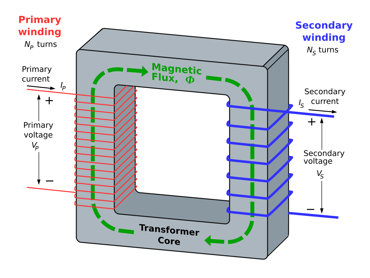
Transformer: Transformer is an electrical device which transfers electrical energy through inductively coupled conductors. These inductive conductors are called coils. From Faraday's Law, we know if we give a varying current in the first or primary winding then in the core a varying magnetic flux will be induced. Thus it will induce a varying magnetic field in secondary winding. This varying magnetic field induces a varying electromotive force (EMF), or "voltage". This effect is known as inductive coupling.


Current will flow in the secondary winding, if a load is connected to it, and from the primary circuit through the transformer to the load electrical energy will be transferred . The induced voltage of an ideal transformer in the secondary winding (Vs) is in proportion to the primary voltage (Vp). It is given by the ratio which is usually called as transformer's turns ratio. The  turns ratio is ratio of the number of turns in the secondary (Ns) to the number of turns in the primary (Np) as follows:


By appropriate selection of the turns ratio, a transformer enables an alternating current (AC) voltage to be "stepped up" or "stepped down" by making Ns greater than Np, or by making Ns less than Np respectively. In most of the transformers, the windings are coils wound around a ferromagnetic core.


Transformers can be of different sizes. One can be size of a thumbnail hidden inside a stage microphone, while other can be huge units weighing hundreds of tons used to interconnect portions of power grids. But all of them operates according to the same principles. 


Now-a-days new technologies have somehow eliminated the need for transformer in some electronic circuit. But still transformers are found in almost all electronic devices which are designed for household use. Transformer are must for high voltage electric power transmission. It makes long distance transmission economical and practical.