

Direct Current machines are energy transfer devices.
These machines can function as either a motor or a generator
Two related physical principles underlie the operation of generators and motors. The first is the principle of electromagnetic induction discovered by the British scientist Michael Faraday in 1831. If a conductor is moved through a magnetic field, or if the strength of a stationary conducting loop is made to vary, a current is set up or induced in the conductor. The converse of this principle is that of electromagnetic reaction, first observed by the French physicist Andr Marie Ampere in 1820. If a current is passed through a conductor located in a magnetic field, the field exerts a mechanical force on it.
Construction
DC motors and generators have the same basic construction, differing primarily in the energy conversion.
The basic requirements are a conductor, flux and relative motion between them. The physical structure of the machine consists of 2 parts: the stator and the rotor. The stationary part consists of the frame, and the pole pieces, which project inward and provide a path for the magnetic flux.
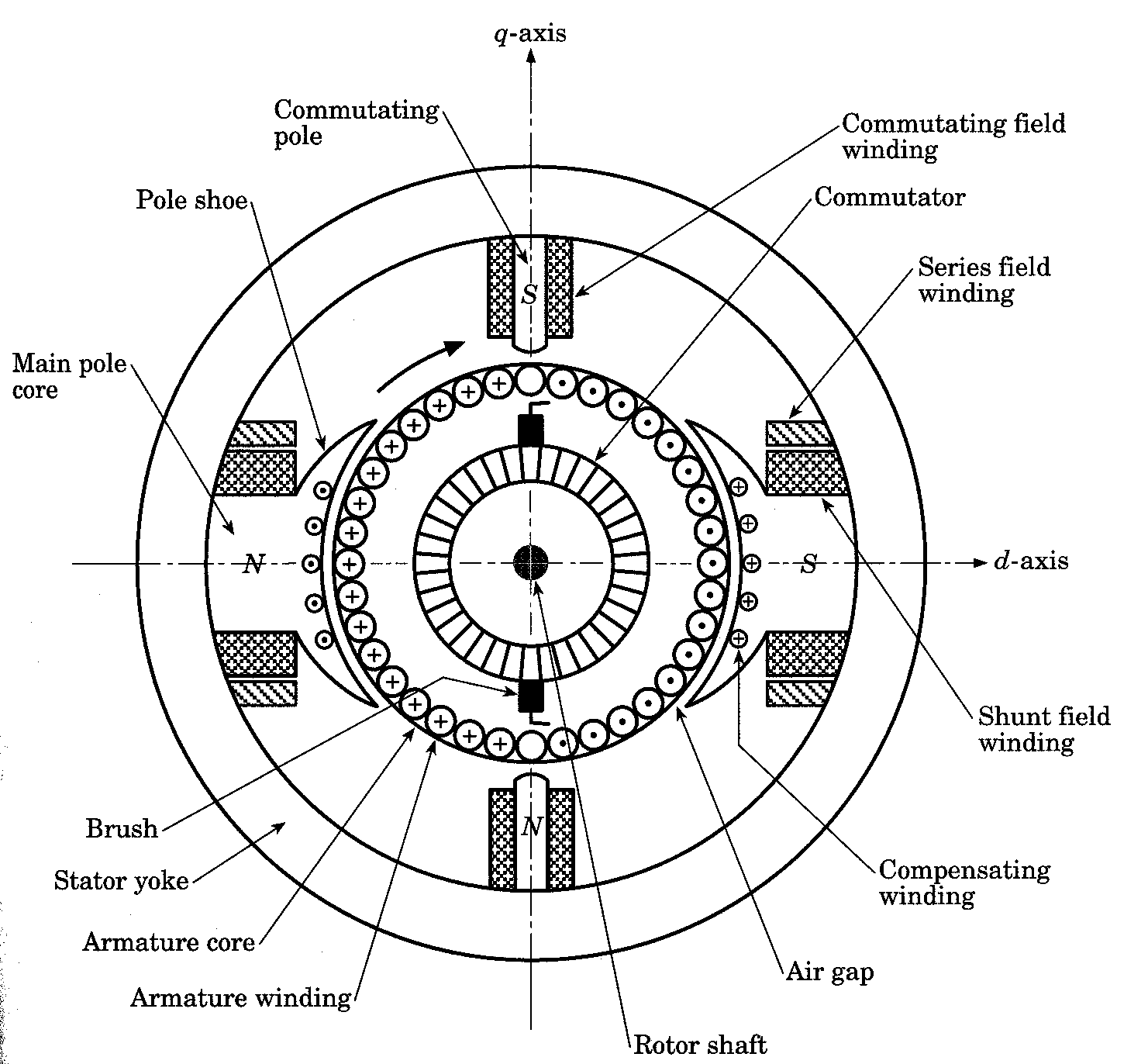
- Frame or Yoke
- Pole and pole shoe
- Field coils
- Armature core
- Armature winding
- Commutator
- Brush and holders
- Shaft and bearings
- Fan or cooling system

Yoke: Made of cast iron or fabricated rolled steel or steel casting. It act as magnetic return path, holds the poles in position and provides mechanical protection
Pole and pole shoe: They are made of MS sheets or laminated soft steel sheets punched to suitable size and stacked and riveted together. Field winding is placed on the poles. The pole shoe serves the purpose of spreading the magnetic field uniformly in the air gap.
Field coils: It is used to produce magnetic field. It is wound on a former and then placed on the pole. Insulated copper wires are used for winding. In the case of compound machine both series and shunt winding are done on the same pole.
Armature core: The primary function is to provide magnetic path of low reluctance. It is made of stamping of circular sheet steel discs of approximately 0.5 mm thickness. The slots are cut on the armature core. Slots may be open or semi closed.

Armature winding: Winding is done through the slots on the armature core and is connected in succession to a Commutator segment. There are mainly two types of winding namely Lap winding and Wave winding.
Commutator and brush: It is a extension of armature to which the connections of armature winding is soldered. A brush touching the Commutator collects the current as it rotates. They are made of segments of copper bars arranged to from a cylinder and each segment is insulated from each other. The type of brush used depends on the speed of rotation. Normally carbon brushes are used. Other brushes used are, Graphite, Metal Carbon, etc.

No comments:
Post a Comment