Showing posts with label DC machine. Show all posts

Sunday, January 17, 2016

January 17, 2016

What is meant by excitation?

"Self Excited vs Magneto". Licensed under PD-US via Wikipedia
Electric generators work on the principle of electromagnetic induction. The essential part of this principle is the magnetic field. The magnetic field is produced from a d.c. power source from an exciter that is part of the generator system. The main requirement for electricity generation as per the basic principle is a magnetic field. The generator while producing electricity also has to produce the excitation current at a constant voltage for the electrical system to work properly. Controlling the magnetic field controls the voltage output of the generator.
The rotor or field coils in a generator produce the magnetic flux that is essential to the production of the electric power. The rotor is rotating electromagnet that requires a d.c. electric power source to excite the magnetic field. This power comes from an exciter.
Exciter is a device that provides a magnetizing current for the electromagnets in a motor or generator. There are two types of exciter, static exciter and rotory exciter. Rotory exciter is an additional small generator mounted on shaft of main generator. It will supply d.c. voltage to the rotory poles through slip ring and brushes. If it is an a.c. exciter, output of a.c. exciter is rectified by rotating diodes and supply d.c. to main field poles.

Monday, January 11, 2016

January 11, 2016

Torque Equation of D.C. Motor

In D.C. machine it is seen that the machine torque is uniform for given flux per pole and armature current. Torque is defined as the product of force with its radial distance at which it acts.
T = F � r
But
F = BIL...Newton
where,
B = flux density in Wb/m2
I = current through armature conductor in Amp
L = Length of armature conductor
r = radius of armature drum.
Considering,
P = Total number of poles
F = Flux cut per pole in Wb
Z = Total number of armature conductor
A = Number of parallel paths
Ia = Armature current
Flux density formula.jpg
Formula for current in DC Machine

Substituting the values of B and I we get,
Torque equation of DC Motor
Torque Equation of DC Motor.jpg
Since Z are the total number of conductors, therefore total torque is given by
Torque Equation of DC Motor
This is known as torque equation of D.C. motor. But P, Z and A are constant hence,
T ? FIa
Thus the torque produced by a D.C. Motor is directly proportional to main flux F as well as armature current Ia.

Friday, January 8, 2016

January 08, 2016

Back E.M.F.

What is Back e.m.f. ?

When the armature of a dc motor rotates under the influence of the driving torque, the armature conductor move through the mangetic field and hence e.m.f. is induced in them as in generator. The induced e.m.f. acts in opposite direction to the applied voltage V (by Lenz's Law) and is known as back e.m.f. or counter e.m.f. Eb. The value of back emf depends upon the speed of rotation of armature conductors.

Significance of Back e.m.f.

The presence of back e.m.f. makes the d.c. motor a self regulating machine i.e., it makes the motor to draw as much armature current as is just sufficient to develop the torque required by the load. The back e.m.f. is always less than applied voltage.
Let,
V = Applied voltage
Eb = Back e.m.f.
Ra = Resistance of armature conductor
Then the current in the armature conductor Ia at any instant is given by,
Ia = Net voltage/Resistance
=V-Eb/Ra
OR V = Eb + IaRa 
When the motor is running on no load small torque is required to overcome the friction and windage losses. Therefore, the armature current is Ia small and the back e.m.f. is nearly equal to the applied voltage. If the motor is suddenly loaded the first effect is to cause the armature to slow down. Therefore the speed at which the armature conductors move through the field is reduced and hence the back e.m.f. Eb falls. The decreased back e.m.f. Eb allows larger current to flow through the armature and larger current means increased driving torque. Thus, the driving torque increases as the motor slows down. The motor will stop slowing down when the armature current is just sufficient to produce the increased torque required by the load.

If the load on the motor is suddenly decreased, the driving toque is momentarily in excess of the requirement so that armature is accelerated. As the armature speed increase and causes the armature current Ia to decrease as back e.m.f. increases too. The motor will stop accelerating when the armature current is just sufficient to produce the reduced torque required by the load.

It follows, therefore, that back e.m.f. in d.c. motor regulates the flow of armature current i.e., it automatically changes the armature current to meet the load requirement.

Wednesday, December 30, 2015

December 30, 2015

Star Delta Starter

If normal supply voltage is applied to the stationary motor then a very large initial current is taken by the stator for short while. This will lead to excess copper losses in the winding which will overheat the motor. This will produce line voltage drop, that in turn, will affect the operation of other electrical equipments connected to the same line and heavy starting current may damage the motor winding. In order to avoid these problem, a starter is used to start the induction motor safely.
Star-Delta Starter
Star-Delta Starter
The motor is designed to operate as delta connected motor under normal conditions. The motor starts as a star connected motor and the voltage per phase is VL/v3. The starting torque is reduced as it is directly proportional to square of stator voltage and there is jerk while switching from star to delta.

Start Mode

The 3 pole 6 way switch is kept in start mode. This will connect terminal R', Y' B' of stator winding to each other. This act as star point. The supply is connected to R,Y,B terminal of the stator winding. Thus in start mode the stator winding is connected to form the star.

Run Mode

The 3 pole 6 way switch is thrown in run position once the motor accelerate. This will connect the terminals in following manner:
R?B', Y?R', B?Y'

Sunday, December 27, 2015

December 27, 2015

Universal Motors

A universal motor is defined as a motor which may be operated on either d.c. or single phase a.c. supply at very high speed in the range of 3000 to 7000 rpm or so. It has starting torque and variable speed characteristics. Universal motor are designed for weak field to minimize commutation difficulties. The stator core is laminated and high resistance brushes are used.
Universal Motor
Universal Motor
Photo Credit www.woodgears.ca

Construction

The construction of universal motor is similar to that of DC Machine. The field poles are mounted on stator winding. Field winding is wound on the field poles. Both the stator field poles and armature is laminated to minimize the Eddy current losses while working on a.c. supply. The armature has straight or skewed slots and the commutator and brush arrangement is resting on it. 
Universal Motor
Universal Motor - Construction

Working

Such motors develop unidirectional torque regardless of whether they operate on A.C. or D.C. supply. The motor runs on the same principle as d.c. motor i.e., force between the main pole flux and the current carrying armature conductor. The universal motor produces the electric torque proportional to the quadrate of the supply current. Since the same current flows through the field winding and the armature, it follows that ac reversals from positive to negative, or from negative to positive, will simultaneously affect both the field flux polarity and the current direction through the armature. This means that the direction of the developed torque will remain positive, and rotation will continue in the same direction. Thus, a universal motor can run both on dc and ac. So the electric torque has the same torque direction at any current polarity and in addition at AC power. The starting torque of a universal motor is determined by the current that flows through the armature and field windings. Due to the inductive reactance of these windings the AC starting current will always be less than the DC starting current.Consequently, the starting torque on AC power will be lower than the starting torque on DC power. The characteristics of universal motor are very much similar to those of D.C. series motors, but the series motor develops less torque when operating from an A.C. supply than when working from an equivalent D.C. supply.

Torque-Speed Characteristics

Torque Speed Characteristics of Universal Motors
Torque speed characteristics of Universal Motor

Application

  1. Universal motors are used in most hand held power tools such as jigsaw, routers, drills and sanders.
  2. They also find their use in household appliances like vacuum cleaner, drink and food mixers and sewing machine. 

Friday, December 18, 2015

December 18, 2015

Electrical DC Machines Operating Principle

The basic principle of a DC machine is Faraday's laws of electromagnetic induction. According to these law, when an conductor moves in a magnetic field it cuts magnetic lines force, due to which an emf is induced in the conductor. The magnitude of this induced emf depends upon the rate of change of flux (magnetic line force) linkage with the conductor.When the armature rotates, the armature conductors cut the flux produced by the field windings (poles). Hence an emf is induced in the armature winding. The direction of induced current is given by Fleming's right hand rule.
  
Let          F = Flux per pole in Wb
               Z = Total number of conductors on the armature
               P = Number of poles
               A = Number of parallel paths on the armature
               ( = P for Lap and = 2 for Wave)
               N = Speed of rotation of armature in rpm
               E = Average emf induced
Then, total flux cut by a conductor taking one complete revolution,
                                     d F = P F
Time taken for one complete revolution,
                                                       dt = 60/N seconds
According to Faraday law of electromagnetic induction,
Emf induced per conductor,
                                                

If there is Z number of conductors connected in A number of parallel paths,
                                                 volts
Since, A, P, Z are constants,
                                                            E a N F

Sunday, December 6, 2015

December 06, 2015

Basic Construction and Working of a DC Machine

dcmotor

Direct Current machines are energy transfer devices.
These machines can function as either a motor or a generator
Two related physical principles underlie the operation of generators and motors. The first is the principle of electromagnetic induction discovered by the British scientist Michael Faraday in 1831. If a conductor is moved through a magnetic field, or if the strength of a stationary conducting loop is made to vary, a current is set up or induced in the conductor. The converse of this principle is that of electromagnetic reaction, first observed by the French physicist Andr Marie Ampere in 1820. If a current is passed through a conductor located in a magnetic field, the field exerts a mechanical force on it.

Construction

DC motors and generators have the same basic construction, differing primarily in the energy conversion.
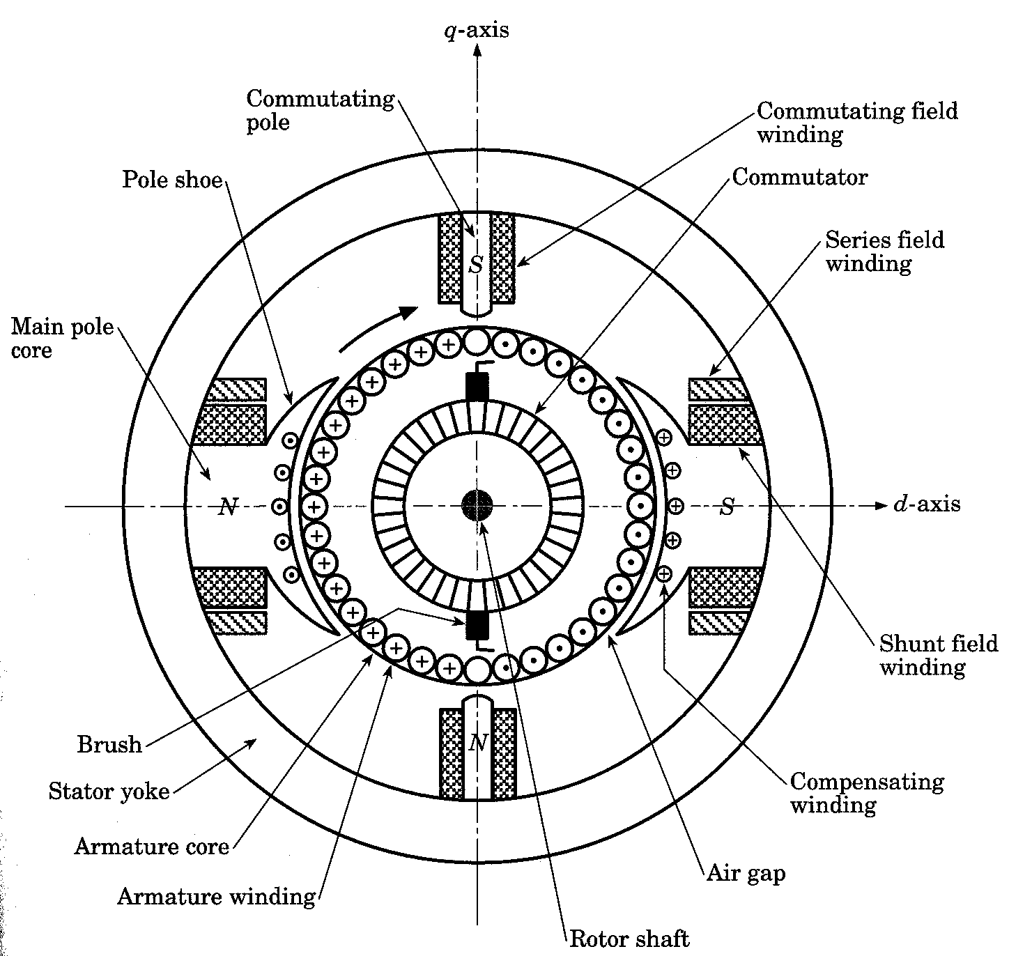
The basic requirements are a conductor, flux and relative motion between them. The physical structure of the machine consists of 2 parts: the stator and the rotor. The stationary part consists of the frame, and the pole pieces, which project inward and provide a path for the magnetic flux.

dcmachine1
The essential parts of a DC machine are:
  1. Frame or Yoke
  2. Pole and pole shoe
  3. Field coils
  4. Armature core
  5. Armature winding
  6. Commutator
  7. Brush and holders
  8. Shaft and bearings
  9. Fan or cooling system
stator
Yoke: Made of cast iron or fabricated rolled steel or steel casting. It act as magnetic return path, holds the poles in position and provides mechanical protection

Pole and pole shoe: They are made of MS sheets or laminated soft steel sheets punched to suitable size and stacked and riveted together. Field winding is placed on the poles. The pole shoe serves the purpose of spreading the magnetic field uniformly in the air gap.
Field coils: It is used to produce magnetic field. It is wound on a former and then placed on the pole. Insulated copper wires are used for winding. In the case of compound machine both series and shunt winding are done on the same pole.
Armature core: The primary function is to provide magnetic path of low reluctance. It is made of stamping of circular sheet steel discs of approximately 0.5 mm thickness. The slots are cut on the armature core. Slots may be open or semi closed.

rotor
Armature winding: Winding is done through the slots on the armature core and is connected in succession to a Commutator segment. There are mainly two types of winding namely Lap winding and Wave winding.

Commutator and brush: It is a extension of armature to which the connections of armature winding is soldered. A brush touching the Commutator collects the current as it rotates. They are made of segments of copper bars arranged to from a cylinder and each segment is insulated from each other. The type of brush used depends on the speed of rotation. Normally carbon brushes are used. Other brushes used are, Graphite, Metal Carbon, etc.

Sunday, November 1, 2015

November 01, 2015

Commutation in DC Machine


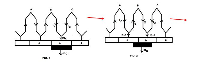
One can be aware of the fact that emf induced into the rotating conductor or winding is always sinusoidal or alternating in nature. If the machine is of DC nature that is DC Generator then it is bounding for someone to convert it (sinusoidal emf) into a unidirectional emf. This process of converting AC voltage into a DC is commonly called as commutation. Hence the commutator is a device which normally acts like a rectifier and perform the process of rectification. Coil(s) current is constant and unidirectional so long as the coil is under the influence of given pole pair(s), while it reverses when the coil passes onto the next pole pair as the armature rotates. Commutation take place when the coil is passing through the interpolar region and during this period the coil is shorted via the commutator segments by the brushes located (electrically) in the interpolar region. Commutation takes place simultaneously for P coils in a lap wound machines and two coil sets of  P/2 coils each in a wave wound machine.
Various symbols used in the figure are:
Ic = coil current 
             Ib = 2Ic = Brush current 
                                       Wc = Width of one commutator segment 
                                                       Wm = Width of mica insulation between segments 
    Wb = Brush width 
                                  Vc = peripheral speed of commutator
commutation-process-Fig (1)
Commutation Process-2

At the instant the commutation of the coil begins, the leading tip of the brush makes full contact with the segment x and is just going to make contact with the segment y. At this instant all coils to the right of segment x carry current Ic flowing from left to right and those on the left current Ic in the opposite direction.
During this period of commutation as the coil passes from right to the left of the brush, the coil current must reverse and the brush should short circuit the coil via segments x and y. The contact width xc between brush and segment x reduces linearly while the contact width yc between brush and segments y increase. The coil current ic(t) during this period is changing. If at the end of the commutation period, when the trailing tip of the brush is going to break contact with segment x. At the end of commutation period, the coil current has not reversed and acquired full value Ic but as Ic' < Ic, the breaking of current (Ic-Ic') at the trailing brush tip takes place causing sparking.
Hence sparking at the brushes which results in poor commutation is due to the inability of the current in the short circuited coil to reverse completely by the end of the short circuited period.

Two methods are available for improving commutation:-

Resistance Commutation

In this method the low resistance copper brushes are replaced by comparatively high resistance carbon brushes.

E.m.f. Commutation

In this method an arrangement is made to neutralise the reactance voltage by producing a reversing e.m.f. in the short-circuited coil under commutation.

For better understanding of what is commutation refer the following videos:-