Showing posts with label Earthing. Show all posts

Saturday, January 2, 2016

January 02, 2016

How a Residual Current Device (RCD) Works

RCD means Residual Current Device. They are so called because they work based on the residual current in a circuit. The RCD is an electrical safety device specifically designed to immediately switch the electrical current flow when current "leaking" to earth is detected at a level harmful to a person using electrical equipment. An RCD offers a high level of personal protection from electric shock.

RCDs also help to reduce the risk of fire by detecting electrical leakage to earth in electrical wiring and accessories. RCDs are designed to operate within 10 to 50 milliseconds and to disconnect the electricity supply when they sense harmful leakage, typically 30mA

RCD Operating Principle
In absence of an earth fault,
the vectorial sum of the currents (I1 + I2) is equal to zero; in case of an earth fault if the (I1 + I2) value exceeds the rated residual operating current I?n, the circuit at the secondary side of the toroid sends a command signal to a dedicated opening or trip coil causing the tripping of the circuit-breaker.

Types of Residual Current Devices (RCD)
There are three basic types of RCDs:
1. Switchboard mounted
2. Power point type and
3. Plug in (portable).
Switchboard mounted and power point types are referred to as non-portable RCDs. Portable RCDs are plugged into a fixed socket. A non-portable RCD installed at the switchboard is the best option in most wiring situations �residential & industrial - as it protects all the wiring and appliances plugged into the circuit.

Switchboard Mounted RCDs
These are non-portable units installed at the switchboard to provide protection of the complete installation, or protection of a selected circuit.

Power point (Fixed Socket Outlet units) RCDs
These are non-portable units consisting of RCD protection inbuilt into a fixed socket outlet to provide protection to equipment plugged into the outlet.

Portable Units RCDs
Various models are available from simple plug adaptors to units designed for specific equipment such as the portable unit.

Sensitivity of RCDs
The sensitivity and speed of disconnection of RCDs are such that any earth leakage will be detected and automatically switched off before it can cause injury or damage. The sensitivity of an RCD in terms of current is given by:


The choice of sensitivity of the RCD is a function of the resistance RE of the earth electrode for the installation. Typical values of RE and sensitivity, I in amps under a fault voltage of 50V and 25V respectively are given below:
I = 50V or 25V/RE


Fault Current Maximum Resistance of the Earth Electrode (RE)
50V 25V
3A 16? 8?
1A 50? 25?
500mA 100? 50?
300mA 166? 83?
30mA 1666? 833?

Limitations of RCDs 
In spite of its versatility and effectiveness, an RCD will not protect against all instances of electric shock. If a person comes into contact with both the active and neutral conductors while handling faulty parts of an electrical installation causing electric current to flow through the person's body, this contact will not be detected by the RCD unless there is also a current flow to earth.

The RCD will only act automatically to disconnect the electricity supply if a fault causes electric current to flow from the active conductor to earth through a person's body.

Wednesday, December 30, 2015

December 30, 2015

Earthing System - Electrical Safety Basics

Earthing is a connection which connects parts of the electric circuit with the ground or earth. Regulations for earthing system vary considerably among countries and among different parts of electric systems. Most low voltage systems connect one supply conductor to the earth (ground). Normally, the earth connection should be without the intervention of a fuse, switch, circuit breaker, resistor etc.

Need For Earthing

  • Stable operation of the system. 
  • Safety of the men and material. 
  • Protection against lightning. 

 Important Terms Relating Grounding

Ground
A ground is a conducting connection, whether intentional or accidental, between an electrical circuit or equipment and earth or to some conducting body that serves in place of earth.
Grounded
Grounded means connected to earth or to some conducting body that serves in place of earth.
Grounded Conductor
A system or circuit conductor that is intentionally grounded, such as grounded neutral conductor.
Grounding Conductor
A conductor used to connect equipment or the grounded circuit of a wiring system to a grounding electrode or electrodes.
Grounded Rod
A conductive metal rod driven in the ground to serve as a grounding electrode, usually 10 to 15 ft long and 1 in. In diameter.
Ground Loop
A continuous ground electrode of wire encircling the area and connecting three or more ground rods.
Ground Clip
A metal clip connected to the ground loop to enable one or more extensions of the ground loop to be extended.
Ground Well
A concrete encasement around the ground rod to allow access to the rod to measure ground resistance.
Ground Grid
A steel mesh or wire grid buried beneath the surface of an area to serve as a ground electrode.
Ground Bus
A metal plate to which multiple ground leads are attached.

Methods Of Earthing

There are two methods of earthing, namely
  1. Pipe earthing 
  2. Plate earthing 

Pipe Earthing

Pipe earthing is done by permanently placing a pipe in wet ground. The pipe can be made of steel, galvanized iron or cast iron. Usually GI pipes having a length of 2.5 m and an internal diameter of 38 mm are used. The pipe should not be painted or coated with any-non-conducting material.


The pipe should be placed at least l.25 m below the ground level and it should be surrounded by alternate layers of charcoal and salt for a distance of around 15 cm. This is to maintain the moisture level and to obtain lower earth resistance. The earth lead of sufficient gauge should be firmly connected to the electrode and it should be carried in a GI pipe at a depth of 60 cm below the ground level.

Plate Earthing

The plate electrode should have a minimum dimension of 600 x 600 x 3.15 mm for copper plate or 600 x 600 x 6.3 mm for GI plates. The plate electrode should be placed at least 1.5 m below the ground level. The earth conductor is to be securely connected to the plate by means of bolts and nuts. The bolts and nuts should be of the same material as that of the plate. The earth conductor should be carried in a GI pipe buried 60 cm below the ground level. The prate electrode should be surrounded by a layer of charcoal to .reduce the earth resistance.


Sunday, December 27, 2015

December 27, 2015

Types of Earthing Systems Used in Electrical Installations

The international standard IEC60364, part 4, and Reference 10 uses a set of diagrams to explain the five basic methods of earthing and providing the neutral of an electrical installation where it is required. The five methods are abbreviated TNC, TNS, TNCS, TT and IT.

The first letter denotes the source of power from a star-connected winding. T denotes that the star point of the source is solidly connected to earth, which is usually at a location very near to the winding.
I denote that the star point and the winding are isolated from earth. The star point is usually connected to an inductive impedance or resistance. Capacitive impedance is never used.

The second letter denotes the consumer. The consuming equipment needs
to be earthed. There are two basic methods that can be used to earth the body of electrical equipment. These methods are denoted by the letters T and N. The letter N is sub-divided into other letters, S and C, thus giving NS and NC and NCS.

T denotes that the consumer is solidly earthed independently of the source earthing method.

N denotes that a low impedance conductor is taken from the earth connection at the source and routed directly to the consumer for the specific purpose of earthing the consuming equipment.

S denotes that the neutral conductor routed from the source is separate from the protective earthing conductor, which is also routed from the source. This implies that five conductors need to be routed for a three-phase consumer.

C denotes that the neutral conductor and the protective earthing conductor are one and the same conductor. This means that four conductors need to be routed for a three-phase consumer.

 The different earthing types are illustrated with the diagrams that now follow:
(a) TNC Earthing System

(b) TNS Earthing System
(c) TNCS Earthing System
(d) TT Earthing System
(e) IT Earthing System

Saturday, December 26, 2015

December 26, 2015

How to Measure Soil Resistivity

Wenner�s four-electrode method is popularly used to measure soil resistivity. In this method Four electrodes are driven into the earth along a straight line at equal intervals, S. The depth of the electrodes in the ground is always of the order of 10 to 15 cm. The earth megger is placed on a steady and approximately level base. The four electrodes are connected to the earth megger terminal as shown below:

A current, I , is passed through the two outer electrodes C1 & C2 and earth. A voltage difference V, is observed between the two inner electrodes PI & P2. The current I flowing into the earth produces an electric field proportional to its density and to the resistivity of the soil. The voltage V measured between the inner electrodes is, therefore, proportion to the field. Consequently, the resistivity will be proportional to the ratio of the voltage to the current, i.e., R.
The soil resistivity is then calculated as:


Where:
? =  Soil Resistivity of soil in Ohms-meter
S = distance between two successive electrodes in    meters
R = ratio of voltage to current or electrode resistance in Ohms
e = depth of burial of electrode in the ground
If the separation distance of the electrodes , S, is much greater than the depth of burial, e, of electrodes, then equation 1 above reduces to :
Modern equipment used for testing for soil resistivity use the Wenner four electrode system and the mathematical calculation above, is done automatically by these new set of equipment such that once setup properly, at the press of a button, the value of the soil resistivity is determined quickly.

Sunday, December 13, 2015

December 13, 2015

Soil Resistivity Values for Different Types of Soil

One key determinant of a good earthing installation is the soil resistivity of the soil where the earth electrode is installed. If you are involved  in earthing buildings and electrical installations, here is a list of the typical soil resistivity values for different types of soil that you might encounter:

Type of Soil Mean Value of Resistivity in ?m
Swampy soil, bogs 1 - 30
Silt alluvium 20 - 100
Humus, leaf mould 10 - 150
Peat, turf 5 - 100
Soft clay 50
Marl and compacted clay 100 - 200
Jurassic marl 30 - 40
Clayey sand 50 - 500
Siliceous sand 200 - 300
Stoney ground 1,500 - 3,000
Grass-covered-stoney sub-soil 300 - 500
Chalky soil 100 - 300
Limestone 1,000 - 5,000
Fissured limestone 500 - 1,000
Schist, shale 50 - 300
Mica schist 800
Granite and sandstone 1,500 - 10,000
Modified granite and sandstone 100 - 600
Fertile soil, compacted damp fill 50
Arid soil, gravel, uncompacted non-uniform fill 500
Stoney soil, bare, dry sand, fissured rocks 3,000
December 13, 2015

How to Use Earthing Rods for Earthing Improvement

Vertically driven conductors called Earthing Rods are commonly used in earthing existing buildings and for improving or reducing electrical resistance of existing earth electrodes. See common terms used in earthing to gain understanding of earthing rod and earth electrode.

Characteristics of Earthing Rods
The rods used for earthing buildings may be:
(a) Copper or more commonly Copper clad steel. Copper clad steel are generally 1 or 2 meters long and provided with screwed ends and sockets in order to reach
considerable depths, if
necessary (for instance, the water-table level in areas of high soil resistivity).

(b) Galvanized steel pipe greater than or equal to 25mm in diameter or rod greater than or equal to 15mm in diameter with lengths greater than or equal to 2 meters long. Note however that where galvanized conducting materials are used for earth electrodes, sacrificial cathodic protection anodes may be necessary to avoid rapid corrosion of the electrodes where the soil is aggressive.

When earthing is done by rods, It is often necessary to use more than one rod as shown above, in which case the spacing between them should exceed the depth to which they are driven, by a factor of 2 to 3.

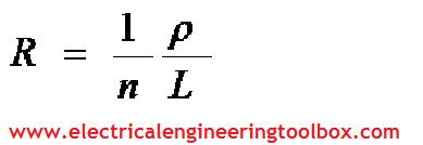
The total resistance (in homogeneous soil) is then equal to the resistance of one rod, divided by the number of rods in question. The approximate resistance R obtained is given by:


Where:
L = the length of the rod in meters
? = resistivity of the soil in ohm-meters.
n = the number of rods

Use of Vertical Plates
Rectangular plates, each side of which must be greater or equal to 50cm, are commonly used as earth electrodes, being buried in a vertical plane such that the center of the plate is at least 1 meter below the surface of the soil.
The plates may be:
(a) Copper of 2mm thickness or
(b) Galvanized steel of 3mm thickness
The approximate resistance, R, in ohms is given by:

Where:
L = the perimeter of the plate in meters
? = resistivity of the soil in ohm-meters.

Tuesday, August 5, 2014

August 05, 2014

Common Terms Used in Earthing/Grounding of Installations- Standard Practice

Earthing or Grounding of electrical installation is a common practice. However, some common terms used in the practice could sometimes be tricky. Here, we have attempted to provide explanations for some of the more common terms used when earthing or grounding an installation. These terms are the ones used in the various national and international standards:
Earthing an Electrical Installation
To understand some of these terms, the schematic above will be very helpful:
Earth electrode 
This is the conductor or group of conductors in intimate contact with, and providing an electrical connection with Earth.

Earth
This is the conductive mass of the Earth, whose electric potential at any point is
conventionally taken as zero.

Electrically independent earth electrodes
These are earth electrodes located at such a distance from one another that the maximum current likely to flow through one of them does not significantly affect the potential of the others.

Earth Electrode Resistance
This is the contact resistance of an earth electrode with the Earth.

Earthing Conductor 
This is a protective conductor connecting the main earthing terminal of an installation to an earth electrode or to other means of earthing.

Exposed-conductive-part 
This is the conductive part of equipment which can be touched and which is not a live part, but which may become live under fault conditions. Usually all exposed conductive parts are connected to the earth electrode by protective conductors with the object of providing a low resistance path for fault currents flowing to earth.

Protective conductor 
This is the conductor used for some measures of protection against electric shock and intended for connecting together any of the following parts:
(a) Exposed-conductive-parts
(b) Extraneous-conductive-parts
(c) The main earthing terminal
(d) Earth electrode(s)
(e) The earthed point of the source or an artificial neutral

Extraneous-conductive-part
This is a conductive part liable to introduce a potential, generally earth potential, which is not part of the electrical installation. Examples of extraneous conductive parts include:
(a) Non-insulated floors or walls, metal framework of buildings
(b) Metal conduits and pipework (not part of the electrical installation) for water, gas, heating, compressed-air, etc. and metal materials associated with them.

Bonding conductor 
This is the protective conductor providing equipotential bonding.

Main Earthing Terminal
This is the terminal or bar provided for the connection of protective conductors, including equipotential bonding conductors, and conductors for functional earthing, if any, to the means of earthing.

Equipotential bonding 
Equipotential bonding simply means terminating all the extraneous conductive parts to the earthing system of the installation in a process referred to as bonding. 
Bonding is carried out by protective conductors and the aim is to ensure that,
in the event of an incoming extraneous conductor (such as a gas pipe, water pipe etc.) being raised to some potential due to a fault external to the building, no difference of potential can occur between extraneous-conductive-parts within the installation.

Friday, March 11, 2011

March 11, 2011

Earthing Protection systems 1: common terms used

Exposed conductive part
Any accessible metal parts of electrical equipment item other than the live parts
and which can accidentally become live.

Electrical fault
Accidental connection between two points at different potentials, such as
insulation fault.
-->

Fault voltage
Voltage, in case of an insulation fault, across an exposed conductive part and
an earthing reference.

Direct contact
Contact of persons with the normally live parts of electrical equipment

Non direct contact
Contact of persons with exposed conductive parts accidentally live due to an
insulation fault.

Double insulation
Insulation including both:
� Basic insulation required for protection against direct contact, and
� Supplementary insulation required for protection against indirect contact in case   of a fault of the basic insulation.


Discrimination
Coordination of the automatic switching devices such that only opening of the
device cuts off the faulty part of the installation located immediately upstream
of the fault.

Protective conductor PE
Conductor used for protection against indirect contact and for interconnecting
exposed conductive parts to one another; to extraneous conductive parts and to earthing electrodes or earthed parts.

Service voltage
The rated operating voltage of a system, which together with the rated current of the system determines the load. For three-phase systems, it is the voltage between phases.


Residual current
In case of an insulation fault, the residual current is the leakage current returned to the source through the earth and the protective conductor.

Residual operating current
Value of the residual current, which causes a residual current device to operate.

Shock protection device
This device must automatically separate from the source any part of the installation on which there is a fault hazardous to life. Depending on the system earthing arrangement of the installation, this device is either a residual current device, or an over-current device (fuse or circuit breaker)