Showing posts with label Power Systems. Show all posts

Tuesday, January 1, 2019

January 01, 2019

Electrical Power, Active, Reactive And Reactive Power

Electrical Power Theory And Formula

Electrical energy is the most usable energy in the modern day. Nowadays the whole world is depended on the electrical energy. Electrical power can be transferred easily and also can be distributed easily. In modern days we cannot live without electrical energy. We use electrical power or electrical energy from starting of the day to the end of the day for lighting, heating and for many others works. The conversion of electrical energy into any other energy is very easy. Today we are going to know all the Electrical Power Theory and Formula.

What is Electrical Power

Electric Power Definition

Electrical power is the rate of transfer of electrical energy into other energy per unit time. In other words, it can be called that the electrical power is the rate of electrical energy consumed by load per unit time.
The standard unit of electrical power is Watt.
According to the definition of electrical power, we can say the basic electrical power formula is
Here, W= power in watt
          Q= charge in coulombs
          V= voltage or electrical pressure in volt
          t=time is sec
We know that the rate of flow of charge per unit time is called current(I)
This is the basic formula of electrical power.
According to the OHM's law, we know that V= I*R
So we can represent the electrical power formula by current(I) and Resistance(R) that is,
We can also represent the formula by voltage(V) and Resistance(R) 

                                            W=

V
2


There are two types of electrical power available according to the nature of the Current,
  1. Direct Current (DC)
  2. Alternating Current(AC)
The DC Power and AC Power have different formulas.

DC Power Formula

DC has a constant value that means the magnitude and direction of current do not change with the time. 
Actually, the electrical power depends upon three important things,
  1. Voltage
  2. Current
  3. The angle between voltage and current
The angle between the voltage and current exists when the circuit consists of an inductor or capacitor. If an electrical circuit consists the only resistor then naturally there will be no angle between the voltage and current but if the circuit consists inductor or capacitor there may be some angle between the voltage and current.
In the DC circuit, there is no angle between voltage and current even if the circuit consists Inductors or capacitors because inductance and capacitance effect does not exist on DC supply. 
So the DC power will be the product of the voltage and current.

electrical power formula for DC


So the DC power formula is, 
P = V*I
Here, P= electrical power in watts
         V= voltage in volts
         I= current in amps.

Power Factor: Power factor is a very important thing when we talk about electric power. Power Factor is the cosine of the angle between voltage and current in an electrical circuit. It is defined as cos f or cos(angle). Here f or angle is the angle between voltage and current.

What is the Power Factor of DC?

As we know that the angle(f) between voltage and current in DC circuit is Zero(0). So the power factor of DC will be cos 0 = 1
As the power factor of the DC is 1 (one) it can not affect the power formula and we always say that the DC has no power factor.

Electrical Power Formula For AC

Now let,s know AC power formula. As the magnitude and direction of the current of AC change with time so the electrical power formula is different. If an AC circuit consists the only resistor then naturally the angle between current and voltage will be Zero but if consists inductor or capacitor there may be some angle between voltage and current.
There are three types of AC Power,
  1. Apparent Power
  2. Active Power
  3. Reactive Power
electrical power formula for AC

Apparent Power

The simple product of the voltage and current of an AC circuit is called Apparent Power. But remember that the value of the voltage and current should be RMS value.
The Apparent power is denoted by 'S'
So the formula of apparent power,
 S=Vrms * Irms

The RMS value of the voltage can be found from the equation,  

The RMS value of the current can be found from the equation,

If the AC circuit only consists resistor then the power can be derived by this equation or in other words for pure resistive circuit the apparent is equal to the active power.
The unit of Apparent power Volt-Ampere.

Active Power

It is the power which actually consumed by the AC Load consist of resistance, inductance, and capacitance. It is denoted by 'P'
Active Power takes the cosine of the angle between the voltage and current into account.
So the active power formula is,
P=Vrms * Irms * cos f

f is the angle between voltage and current
The unit of Active power is Watt

Reactive Power

The power dissipated by the circuit element reactance is called Reactive Power. Suppose an electrical AC circuit consists the only resistor then we can say that circuit has not any reactance but if the circuit consists inductance or reactance then the circuit will have reactance.
The reactive power is denoted by 'Q'
The formula of Reactive power is,
Q=Vrms * Irms * Sin f

The relation between Apparent power, active power, and reactive power can be written as below

Electrical Power Triangle

The electrical power triangle consists,
  1.  Active power in 'X' axis 
  2. Reactive power in 'Y' axis
  3. Apparent power in 'Z' axis
electrical power triangle


Tuesday, January 5, 2016

January 05, 2016

Economics of Power Generation, Transmission, Distribution

Generation and distribution of electrical energy is generally treated as a service to the people and at the same time it is a commercial activity.

Factors Affecting Cost of Generation:

  1.  Constant availability of fuel.
  2. Availability of suitable sites for the power plant.
  3. Cost of the equipment used for installation.
  4. Maintenance requirement of the power plant.
  5. Nature of the load (plant capacity factor, diversity factor etc)
  6. Interest on capital investment.
  7. Manpower requirement.
  8. Extend of interconnection of generating stations.
As a general practice, the total cost of energy generation is accounted in two parts - fixed cost and running cost. Fixed cost includes the overhead due to the installation a part maintenance cost, salary to permanent employees, etc. The running cost depends on the units of energy generated. It includes cost of fuel, a part of maintenance cost, etc.

Terms Associated with Power System:

There are certain parameters, which describe the size and utility of the power system.
  • Connected load
It is the sum of power ratings of all the electrical equipment connected to the system.
  • Maximum demand
It is the highest demand of power in a system during a selected period of time. Maximum demand is usually stated in kW or MW.
In practice, maximum demand taken as the average load over a designated interval of time, say half hour. The average demand is measured for every half an hour interval and highest value out of that is taken as the maximum demand.
  • Demand factor
Demand factor is the ratio of maximum demand to connected load.
Demand factor =Maximum demand/Connected load
  • Average load
For a generating station, the average load is given by the following expression.
Average load = Energy (kWh) generated/Total hours
  • Load factor
It is the ratio of the number of units of electricity actually generated during a period to the number of units that could be generated if the generation is throughout at the maximum demand. Load factor is given by the following expression.
           
Load factor = Energy produced during a given period/Max Demand x Hours of operation

Load factor is also expressed as:
Load factor =Average load/Maximum demand

It is also possible to relate the load factor with the load curve shown in the figure. The area below the load curve (shaded portion) represents the energy produced during the period, whereas the area of the rectangle ABCD is equal to the product of maximum demand and the hours of operation.

  • Diversity factor
Diversity factor indicates how diverse the occurrence of maximum demands of individual consumers is. It is the ratio of sum of maximum demands of the individual consumers to the maximum demand of the system.                  
Diversity factor = Sum of consumers' maximum demands/Maximum demand on the system
  • Plant capacity factor
Plant capacity factor is a measure of the utilization of the power plant's capacity.
                        
Plant capacity factor =  Actual energy generated/Maximum energy that could be generated
  • Plant use factor
It is the ratio of the actual energy generated during a period to the energy that could be generated at the full capacity of the power plant, whenever plant was in operation.   
Plant use factor =Actual energy generated/Plant capacity x hrs of operation
  • Reserve capacity
Some generating capacity should be maintained as standby in the system to meet any increase in power demand. In general we can define the reserve capacity as the installed capacity available above the demand. Depending on the amount and nature of the expected increase, there are different types of reserves as follows.
Cold reserve: This is the generating capacity, which is available for service hut not in operation. Generators on cold reserve will be started only when there is a demand.
Hot reserve: The generating capacity, which is in operation but not in-service. Generators on hot reserve will be running but not connected to the grid.

Spinning reserve: The generating capacity, which is in operation and connected to the grid and is ready to take load. Spinning reserve is maintained to meet any unpredictable sudden increase in load.

Saturday, January 2, 2016

January 02, 2016

Hydroelectric Power Plants - Advantages, Disadvantages

Hydroelectric power plants convert energy available from flowing water into electricity. These power stations are suitable where water resources with sufficient head are available. When water is allowed to flow from the high elevation to a lower elevation, potential energy is transformed into kinetic energy, which is converted into electrical energy by the hydroelectric power plants.
The hydroelectric power plants can be divided into:
  1. Storage based power plants: these are the most common type and can produce electric power in huge quantities. A dam is built across the river bed creating a huge reservoir of water behind it.
  2. Run-off river or diversion power plants: A portion of a river or stream water is diverted to create a difference of elevation. These are small size plants and depend on availability of water for their operation.
  3. Pumped storage power plants: A pumped storage plant operates as a dual action water flow system. When the power demand in a power system is low, a part of energy generated by other power plants in the system is used to pump water from a lower level in front of a dam to a higher level behind the dam. In case of higher electric power demand the water behind the dam is used to produce electrical energy.The major functional parts are explained below. 
Dam or Reservoir
Stops the river's flow and forms a reservoir. The reservoir stores water during rainy seasons. It also helps to maintain a steady water head for the turbine to operate. The water level of the reservoir is called head race.
Tunnel
Tunnel is used to transport water from the reservoir to the generating station. It is normally made of RCC (Reinforced Cement Concrete).
Pen-stock
A penstock is a conduit that takes the water from the reservoir to the powerhouse. It is usually made of steel and is suitable for carrying water at medium to high pressure. For low-pressure penstocks, RCC pipes are also used.
Valve houseThis is a facility to start or stop the water flow into the powerhouse for normal operation and for maintenance.
Surge tank
Surge tank is a small additional storage facility near the powerhouse. When the distance is more, non-uniform water intake to the powerhouse results in water hammering. The surge tank takes the sudden increase of pressure by allowing the water into it, when the water flow is stopped or reduced. Thus the surge tank functions as a pressure regulator in the water line.
Powerhouse
A powerhouse houses the turbine and the generator. The turbine converts the hydraulic energy from flowing water to mechanical energy. The generator, which is mechanically coupled to the turbine, converts mechanical energy to electrical energy. The used water from the turbine is released through the Tail race.
Factors to be considered:
  1. Quantity of water available
  2. Storage facility
  3. Head of water
  4. Accessibility
Advantages of hydroelectric power plants: 
  • No fuel is required for operating a hydroelectric power station. 
  • The generation cost is very low. 
  • Uses simple technology. 
  • Low start up time. 
  • It is a clean source of energy and no pollutants are generated. 
  • Generally hydro plants have longer life compared to other types. 
  • The dam and reservoir serve the purpose of irrigation and flood control also. 
Disadvantages of hydroelectric power plants:
  • It requires large area for installation. 
  • May affect the ecological balance of the area. 
  • High cost of construction. 
  • Long gestation period (time taken to get back returns after making the investment) 
  • The generation is weather dependent.

    Wednesday, December 30, 2015

    December 30, 2015

    Earthing System - Electrical Safety Basics

    Earthing is a connection which connects parts of the electric circuit with the ground or earth. Regulations for earthing system vary considerably among countries and among different parts of electric systems. Most low voltage systems connect one supply conductor to the earth (ground). Normally, the earth connection should be without the intervention of a fuse, switch, circuit breaker, resistor etc.

    Need For Earthing

    • Stable operation of the system. 
    • Safety of the men and material. 
    • Protection against lightning. 

     Important Terms Relating Grounding

    Ground
    A ground is a conducting connection, whether intentional or accidental, between an electrical circuit or equipment and earth or to some conducting body that serves in place of earth.
    Grounded
    Grounded means connected to earth or to some conducting body that serves in place of earth.
    Grounded Conductor
    A system or circuit conductor that is intentionally grounded, such as grounded neutral conductor.
    Grounding Conductor
    A conductor used to connect equipment or the grounded circuit of a wiring system to a grounding electrode or electrodes.
    Grounded Rod
    A conductive metal rod driven in the ground to serve as a grounding electrode, usually 10 to 15 ft long and 1 in. In diameter.
    Ground Loop
    A continuous ground electrode of wire encircling the area and connecting three or more ground rods.
    Ground Clip
    A metal clip connected to the ground loop to enable one or more extensions of the ground loop to be extended.
    Ground Well
    A concrete encasement around the ground rod to allow access to the rod to measure ground resistance.
    Ground Grid
    A steel mesh or wire grid buried beneath the surface of an area to serve as a ground electrode.
    Ground Bus
    A metal plate to which multiple ground leads are attached.

    Methods Of Earthing

    There are two methods of earthing, namely
    1. Pipe earthing 
    2. Plate earthing 

    Pipe Earthing

    Pipe earthing is done by permanently placing a pipe in wet ground. The pipe can be made of steel, galvanized iron or cast iron. Usually GI pipes having a length of 2.5 m and an internal diameter of 38 mm are used. The pipe should not be painted or coated with any-non-conducting material.


    The pipe should be placed at least l.25 m below the ground level and it should be surrounded by alternate layers of charcoal and salt for a distance of around 15 cm. This is to maintain the moisture level and to obtain lower earth resistance. The earth lead of sufficient gauge should be firmly connected to the electrode and it should be carried in a GI pipe at a depth of 60 cm below the ground level.

    Plate Earthing

    The plate electrode should have a minimum dimension of 600 x 600 x 3.15 mm for copper plate or 600 x 600 x 6.3 mm for GI plates. The plate electrode should be placed at least 1.5 m below the ground level. The earth conductor is to be securely connected to the plate by means of bolts and nuts. The bolts and nuts should be of the same material as that of the plate. The earth conductor should be carried in a GI pipe buried 60 cm below the ground level. The prate electrode should be surrounded by a layer of charcoal to .reduce the earth resistance.


    Saturday, December 12, 2015

    December 12, 2015

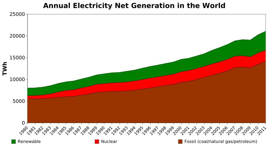
    Electricity Power Generation, Sources of Energy

    The most common method of generating electrical energy is by means of electric machines known as Generators.  Generators used to generate A.C. electrical power are also called Alternators.  These machines are essentially converters which convert mechanical energy into electrical energy. The mechanical energy required to turn on alternator is supplied by machines or devices called prime movers.  Alternator systems are generally named for their prime movers.

    Sources of Energy

    Selection of a particular type of power plant for an area depends on a number of factors like energy demand, availability of fuel, pollution standards and financial considerations.
    Based on the requirement of fuel, energy sources- are broadly classified as renewable energy sources and non-renewable energy sources.
    Renewable energy sources are considered to be available forever. Examples are hydro energy, solar energy, wind energy, wave energy etc. Non-renewable sources use some fuel like coal, which will be available for a limited period of time only.
    Energy sources like solar energy, wind energy, wave energy, tidal energy etc. are relatively new in bulk electricity- generation and therefore arc called non-conventional energy sources.

    900px-annual_electricity_net_generation_in_the_world-svg